2D Design


Choosing a 2D design software wasn't hard for me since I've been using inkscape for a while now. It's a freeware that gives all the necessary features for good 2D draw, the svg format wich inkscape use is also super easy to adapt with all kind of machine and software .
Since I'm already pretty confident with inkscape and it's functionallity, I did not pass to much time on it this week, I just wanted to make a first draw of what my final project could look like.

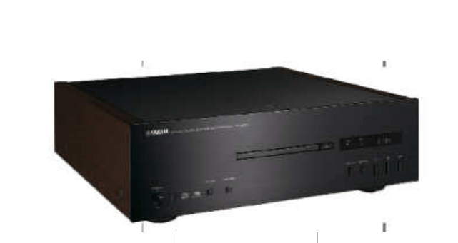
At the begining of the week, I wanted to do a cd player for my final project, not sure if it can be done but that's what I drew this week.

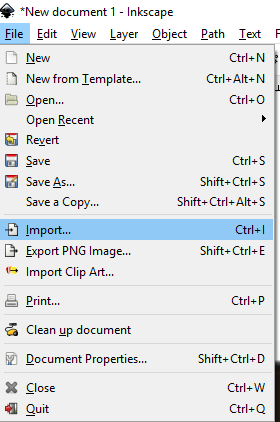
First I found a nice cd player that fit the design I was looking for. I save an image of the cd player as an png and import it in Inkscape.


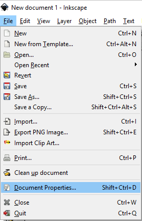
Next, I went into the document propreties to fit my artboard with my import image.


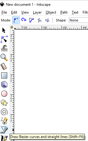
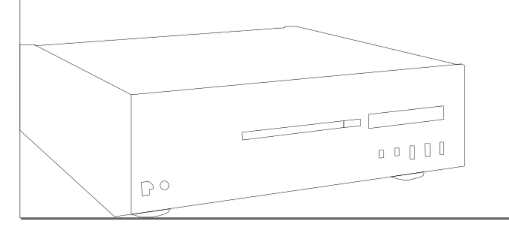
Then I use the bezier/line tool to draw over the picture:


Once my outline was done, I went into the stroke/fill option and set a visible colors to my stroke.


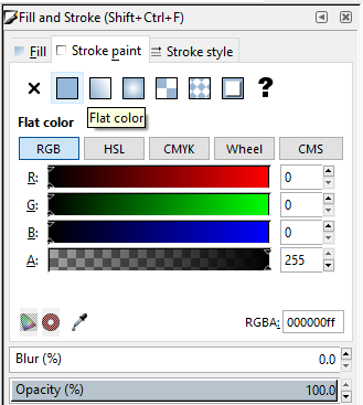
Using the fill tool, I insert color in my draw.


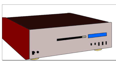
Sure it's really simple and you can go way further with Inkscape, it is trully an amazing software and the community behind it is pretty huge, the program is avaible on all platform and is open source.

Unfortunatly, my computer crash just before I got the chance to save (stupid me!) so I lost my entire file, but this was just a really simple sketch to show I'm able to use the software, I will link my 3D design.

3D Design


I was super excited to jump into the 3D design part of the course. long time ago I did a bit of Blender but did not fell in love with its interface, so I decided to look at other software.

  1. Fusion360
  2. Openscad
  3. Solidworks

  4. I did my design with fusion 360, There were a user at the lab who wanted to 3D print a flexible model, so I used the opportunity to design a chain that would flex on its own. I first made a sketch of a simple polygon and set it's dimension using the sketch and dimension tool.


    Once extrude, I made a shell inside one side of the polygon and sketch and extrude the same hole on all the other side.


    Then I sketch anoter polygone inside the first one and made a trough hole using again the extrude function.


    I then create a plane that would enable me to create body inside the hole of the polygon side.


    I use that new plane to sketch a couple of circle that would fit inside my polygon.


    And the extrude again...


    I let one side of the polygon empty so I could use this space to multiply my patern. For that, I use the rectangular patern function and use it to multiply my model one inside another.

    Using a 3D software for the first time in a while was a really cool thing to achieve, I learn a lot in a short period of time and realise pretty fast that one of the most important thing to do when working with these kind of software is the way you will organize your workflow, let me explain. its important to thing steps ahead when you design, you have to do your work knowing that the mistakes are possible and you might want to change things that you previously done. To simplify this process you might want to design your things using what we called parametric design, this means that when you change a value in your design, everything else will change with it.

    One really important function in Fusion 360 to help you work with parametric design is the change parameters function. This function let you create custom parameters call User Parameter, you will then be able to use these parameters as dimension constraint when you design your things and will be able to change them as any moment of your design process.

    Here is a simple exemple of me doing a rectangle using the change parameters function instead of having to change every dimension contraint when wanting to modify equal constraint in my design.


    We can see here that once I set a parameters, i can change it as long as I want and the design will respect these constraint. This is a really useful function that will be extremely used during my future cad design!

    In fusion 360 there is a difference between a bodie and a component. It can be pretty confusing to determine what purpose and what difference each one have compared to the other. It is altough important to understand those difference if you want to correctly design your projects. To make it simple, here is a small definition of each of them and a link to a more complex and trough definition of those concept.

    The Bodies: Bodies are geometries, that you can create, modify and assemble togheter. You may want to create a door, to do so you would have a bodie that represent the frame of the door and a other bodie that would represent the knob. You would then be able to join them togheter.


    The Components: Component represent real-worlds part, something that can be manufactured. A component can containt bodies, sketches, joints, plane and other object. The finality of a component represent something that could exist in real life.

    There is a ton of thing to know and learn in Fusion 360 it is really a wonderful software that can do a lot of stuff and is always expanding. There is also a great community behind the software and the devs at Autodesk are flawless. here is a few reference site and youtube channel that help me figure it all out!

    My 3D file
    Fusion360 Forums
    Lars Christensen Youtube Channel